Academy · Open FEM Studio course
3D analysis model of a steel structure
In about two hours you learn to draw a steel structure as a 3D analysis model in Open FEM Studio: where nodes belong, which connections are pinned and how to put the loads on it.
After this course of about two hours you can draw a steel structure as a 3D analysis model in Open FEM Studio: you know where nodes belong, which connections are pinned and how to put the loads on it.
How to work with this course
The course has two parts of about an hour each. For every section you first read the explanation; at the end of each part you do an exercise in Open FEM Studio.
| Part | Section | Time (min) |
|---|---|---|
| 1 | What an analysis model is | 10 |
| 1 | Splitting members | 15 |
| 1 | Connections: pinned or rigid | 15 |
| 1 | Stability of a hall | 10 |
| 1 | Exercise: drawing a hall | 20 |
| 2 | Load cases | 10 |
| 2 | From area load to member | 10 |
| 2 | Combinations and imperfection | 10 |
| 2 | Exercise: loads, analysis, checking | 20 |
| 2 | Checklist | 5 |
You need: Open FEM Studio 2026.45 or newer, a mouse with a scroll wheel, and this course next to your screen. You type all lengths in millimetres: 5000, not 5.
You draw the model; the structural engineer decides the design. In doubt about a connection, support or load? Write your question down and ask. A model is always checked by a structural engineer before it is used.
Part 1 — What an analysis model is
An analysis model is a simplified version of the structure: only the parts that carry force, as lines and points. Three building blocks:
- Member — a line with a section and a material, for example an HEA 200 column in S235.
- Node — a point where members are connected to each other, or where there is a support.
- Support — the place where the structure stands on the foundation.
You draw a member on its centre line, the system line, not on the outside of the section. A beam that in reality sits against the flange of a column meets the column in the model where their centre lines intersect. In a hall that difference is negligible; where it does matter, the structural engineer will tell you.
What carries no force, you leave out. Wall cladding, window frames and insulation are not members but a load on the members. Bolts, end plates and welds are not drawn either: they are captured by the choice of pinned or moment-fixed.
From 2D to 3D
In 2D a node has three degrees of freedom: displacement in two directions and rotation. In 3D there are six: three displacements (X, Y, Z) and three rotations. In Open FEM Studio Z points up; X and Y lie in the horizontal plane.
So in 3D you think in every direction. A portal frame that is rigid in its own plane can simply fall over sideways. That comes back under Stability.
Every member also has its own local axes: x along the member, y and z across it. In an I-section one cross axis coincides with the strong axis and the other with the weak axis. Turn on the Local axes and end releases view to see them; if a section is rotated the wrong way, adjust its orientation in the properties panel.
Splitting members: when to and when not to
A node belongs where members are really connected to each other, or where there is a support. Nowhere else.
Two members that cross without a shared node are not connected in the model. They pass through each other and no force goes from one to the other. This is the most common mistake in a 3D model.
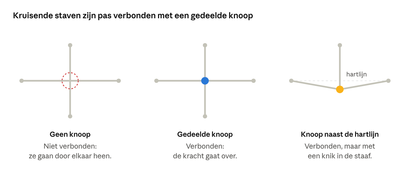
Only with a shared node does force pass between them. If that node lies just off the centre line, the member gets a kink.
A node is needed
- Where another member connects: a purlin on a rafter, a beam on a column, a brace on a column head.
- At a support.
- Where the section changes: then they are two members.
- Where there is a hinge in the line, as in a Gerber beam.
No node needed
- For a load. You can put a point load or line load anywhere on a member, without splitting it.
- To make it tidy. An extra node adds nothing.
What the program does for you
- With the setting Merge and connect nodes automatically the program splits a member itself as soon as you put a node on it, or when a new member runs through an existing node. A point that lies within the connection tolerance of a node (5 mm by default) becomes that node.
- The model check reports a node that lies on a member without being connected to it. Connect splits the member at that node; the ribbon button Connect nodes does this for the whole model at once.
- If a node lies just off the centre line, the member gets a kink there and the program reports it. So snap to nodes and the grid, and check the coordinates.
Watch out — the program does not see this. If two members cross without a node at that spot, the model check reports nothing. The program cannot know whether they are really connected. You have to see it: rotate the model and check at every crossing whether a node belongs there.
Splitting and the buckling length
If you split a member where nothing else connects — same section, in line with each other, no support, no hinge — the program checks the parts again as one member. The buckling length then remains the full length.
If something does connect at that node, such as a purlin or a brace, it is a real node and each part is checked separately. So only connect what is really connected: a purlin fixed to a rafter yes, a pipe that merely runs alongside it no.
Connections: pinned or moment-fixed
Every member end is moment-fixed or pinned. A hinge transfers forces, but no bending moment.
| What passes through the member end | Moment-fixed | Pinned |
|---|---|---|
| Axial force N | yes | yes |
| Shear forces Vy and Vz | yes | yes |
| Torsion Mx | yes | yes |
| Bending moment My | yes | no |
| Bending moment Mz | yes | no |
So in 3D a hinge releases bending about both cross axes. Pinned deliberately keeps torsion fixed: release torsion at both ends and the member can spin freely about its own axis. That is a mechanism, and then the model does not solve.
In steel
Which connection it is, the structural engineer decides; you draw what is on the sketch. As a rule of thumb:
- A fin plate or an end plate without stiffeners, for a beam on a column: pinned.
- A welded or heavily bolted rafter corner with stiffeners or a haunch: moment-fixed.
- A brace: pinned at both ends. A slender rod or strip that can only take tension gets Tension only: under compression it does not take part and the program shows it as inactive.
In the program
- Properties panel, End releases: Moment-fixed or Pinned, for both ends at once.
- Tool Member-end hinge: makes one end pinned; another click makes it fixed again.
- Ribbon button Pin beams: makes every beam end on a column head pinned in one go. Columns stay continuous. If part of the structure would then swing away, such as a canopy hanging from a single column head, the program leaves that end moment-fixed and reports it.
- The Local axes and end releases view shows where every hinge is.
Supports
At a support too, you choose what is fixed and what may rotate.
- Spatial pin — no displacement, rotation is free. A column base with a small base plate and four anchors is usually calculated this way.
- Fixed — nothing can displace or rotate. Only if the base and the foundation are designed for it.
- Hinge about X, Y or Z or a roller — only if the sketch says so.
If you choose a fixed support that does not exist in reality, the structure looks stiffer and stronger than it is. In doubt, choose the pin and check.
Stability: how a hall stays up
A hall only stays up if in both directions it has a path to bring horizontal forces, such as wind, down to the foundation.
Wind pushes against the walls. That force has to reach the supports through members and connections. If that path is missing in one direction, the hall falls over in that direction; in the model this is called a mechanism.
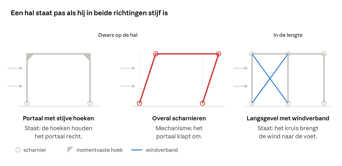
Across the hall the rigid rafter corners keep the portal upright; lengthwise the wind bracing does. With only hinges the structure collapses.
Across: the portal frames
Across the hall the portal frames carry the wind: two columns with a rafter on top. A portal only stands if it is rigid, with moment-fixed rafter corners or fixed column bases. A portal with hinges everywhere is a parallelogram that simply folds over.
Lengthwise: the wind bracing
Lengthwise the portal frames are only linked by purlins and hinges, and there they carry nothing. That is what wind bracing is for: crosses of rods or strips in the roof and in the side walls, usually in an end bay.
The path of the force: the wind on the gable wall goes through the purlins to the roof bracing, the roof bracing takes it to the wall bracing, and the wall bracing takes it to the foundation. A brace always runs from node to node, never to a point halfway along a member without a node.
A concrete floor or a stiff roof deck can also provide stability; in the program this is a diaphragm. Only use one if the structural engineer says so.
How you notice it
If a path is missing, the program warns about a mechanism. Then check in which direction the model is not held. It is almost always a forgotten brace, one hinge too many, or a crossing without a node.
With crosses of tension-only members there is one more cause. Under vertical load alone the columns become a fraction shorter, and then both diagonals of a cross are slightly in compression. The program then switches them both off and the bay loses its bracing. The check always runs second order, and then reports a mechanism while your model is fine. So turn on the Cross rule: of each cross, the diagonal with the largest axial force then stays active.
Exercise part 1: drawing a small hall
You draw a hall 12 m wide, 12 m long and 5 m high, with a flat roof: three portal frames 6 m apart. The sections are only for the exercise and have not been designed.
| Part | Section | Material | Connection |
|---|---|---|---|
| Columns | HEA 200 | S235 | moment-fixed to the rafter |
| Rafters | IPE 360 | S235 | moment-fixed to the columns |
| Purlins, 3000 mm centres | IPE 160 | S235 | pinned |
| Wind bracing | RD 16 | S235 | pinned, tension only |
X is the width, Y the length, Z the height. The portal frames are at Y = 0, Y = 6000 and Y = 12000.
- Create a new 3D project. In the settings, turn on Merge and connect nodes automatically and leave the connection tolerance at 5 mm.
- Columns. With Add node, place the six bases at Z = 0 and the six heads at Z = 5000, in the corners of each portal frame: X = 0 and X = 12000. With Add member, draw from each base to its head.
- Rafters. At each Y, draw a member from head to head, from X = 0 to X = 12000.
- Purlins. Draw them at X = 0, 3000, 6000, 9000 and 12000, and per bay: from Y = 0 to 6000 and from 6000 to 12000. At every end node that falls on a rafter, the program splits that rafter; you see the message … members split at the nodes lying on them.
- Hinges. Select all purlins and choose Pinned in the properties panel. Rafters and columns stay Moment-fixed.
- Supports. Give the six bases a Spatial pin.
- Wind bracing in the first bay, from Y = 0 to 6000. In the roof: one cross from X = 0 to 6000 and one from X = 6000 to 12000, from rafter to rafter. In both side walls (X = 0 and X = 12000): a cross from base to head. Make them Pinned and Tension only. Then turn on the Cross rule in the load case bar; it appears as soon as the model has tension-only members.
- Open the model check. It should show nothing. If there is a node on a member, read why and choose Connect if they are really connected.
- Turn on Local axes and end releases and check every member end against the table above.
Why per bay in step 4? A long purlin from Y = 0 to 12000 crosses the middle rafter without a node. The two are then not connected, and the model check does not report it.
Why not the ribbon button Pin beams? It would also pin the rafters to the columns. With pinned bases the portal is then no longer a portal and the hall falls over sideways.
Check questions
- Why do the rafter corners have to be moment-fixed here?
- What happens if you leave out the wall bracing?
- The roof bracing crosses the purlin at X = 3000 without a node. Is that wrong?
Answers: (1) the bases are pinned, so across the hall only the rigid corner gives stability; (2) lengthwise there is then no path to the foundation: a mechanism; (3) no, in reality they are not connected there either.
Part 2 — Load cases
You put each kind of load in its own load case. The program then combines those cases with safety factors. A new project already has five: Self-weight, Permanent (G), Variable (Q), Snow (S) and Wind (W). You only add what is missing.
Why separate? Snow and wind do not always occur together, and each kind gets its own factor. A case in which everything is lumped together cannot be combined properly by the program.
| Load case | Kind | What it contains | How in the program |
|---|---|---|---|
| Self-weight | permanent | the members themselves | calculated by the program from the section; you do nothing |
| Permanent (G) | permanent | the finishes: roof build-up, wall cladding, services | load panel; the cladding through the envelope panels |
| Variable (Q) | variable | the roof imposed load: people maintaining the roof | Roof imposed load category H in the generator, or a load panel |
| Snow (S) | variable | snow on the roof | Ground snow load sₖ in the generator |
| Wind (W) | variable | pressure and suction on walls and roof | Wind on walls and roof in the generator |
The generator is Generate 3D envelope loads. It creates the load cases and load panels itself, and leaves loads you had already placed by hand in place.
Snow
Throughout the Netherlands the ground snow load is sₖ = 0.7 kN/m². On a flat or shallow roof 80 % of it counts: 0.8 × 0.7 = 0.56 kN/m² on the roof. You enter sₖ in the generator; it calculates the shape coefficient itself.
Wind
How much wind there is depends on the location: the wind zone (I, II or III), the terrain category (coast, open country or built-up) and the height of the hall. Each zone of wall and roof gets its own pressure or suction. Wind can come from different directions, so the generator creates several wind cases.
Leave the structural factor and background leakage at their default values, unless the structural engineer says otherwise.
From area load to member
You put a load in kN/m² on the model with a load panel. The program distributes that load over the beams in the panel and turns it into ordinary line loads.
You draw a load panel with its corners on nodes, and give it a load case and a q in kN/m².
Load direction
- Gravity (−Z), per m² horizontal projection — for snow and roof imposed load. On a sloping roof the area counts as seen from above.
- Vertical (−Z), per m² actual panel area — for the weight of roof sheets on a sloping roof.
- Normal to the panel, per m² panel — for wind. Whether a positive q pushes the wall in or pulls it out depends on how the panel lies. So look at the arrow on the canvas; if it points the wrong way, choose Reverse direction.
Load transfer
- One-way (span) — a roof sheet spans from purlin to purlin. As Span direction choose the direction across the purlins. Each purlin then receives a strip of half the distance to its neighbours: the loaded width.
- Two-way (45° lines) — a slab resting on four edges, such as a floor. Each point goes to the nearest beam, and 45° lines run from the corners.
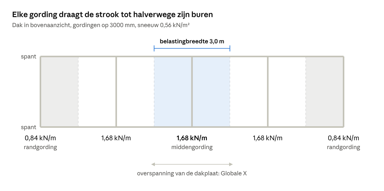
The roof sheet spans from purlin to purlin. An intermediate purlin therefore carries a strip of 3.0 m, an edge purlin half of that.
Under Beams in the panel each member shows what it does: (carries), (parallel, no load) or (skewed, no load). Wind bracing therefore gets nothing automatically. If a member carries nothing in reality, untick it; its share goes to the other beams.
Worked example
Purlins at 3000 mm, snow 0.56 kN/m², one-way across the purlins:
- an intermediate purlin carries 3.0 m: 0.56 × 3.0 = 1.68 kN/m;
- an edge purlin carries 1.5 m: 0.56 × 1.5 = 0.84 kN/m.
Check
Under Derived line loads you see what each member receives. Below it is Total transferred … kN · q × A = … kN: those two numbers should be equal. If they differ, or the program reports an edge without a beam, check whether the panel lies on the right beams.
Combinations, safety factors and imperfection
The program creates the combinations itself. You make sure every load case has the right kind and that nothing is missing.
A combination is a sum of load cases, each with a factor. There are two kinds:
- ULS, the ultimate limit state — is the structure strong and stable enough? With safety factors.
- SLS, the serviceability limit state — does it not deflect too much? Without safety factors.
For new buildings in consequence class CC2, these factors apply in the Netherlands in the ULS:
| Load | Factor |
|---|---|
| Permanent, unfavourable (expression 6.10a) | 1.35 |
| Permanent, unfavourable (expression 6.10b) | 1.2 |
| Permanent, favourable, for example with uplift wind | 0.9 |
| Variable, the leading load | 1.5 |
| Variable, accompanying | 1.5 × ψ₀, with ψ₀ per kind of load |
Each variable load is the leading one in one of the combinations. That is why you see several ULS combinations, plus one for uplift wind in which the self-weight acts favourably (0.9).
The program fills in the ψ₀ factors and the list of combinations itself. You check:
- does every load case have the right kind: permanent or variable, and which type?
- does every variable case appear in the list?
- is there a combination with favourable self-weight for the wind?
Imperfection
No column stands exactly plumb. That is why the program always checks in second order (P-Δ) and with an initial sway imperfection φ: 1/200 by default, adjustable in the project settings. In the report this appears as 2nd order + sway.
Second order means: the program calculates with the deformed shape. A column that leans slightly gets an extra moment from its own load, and the program takes that into account. You do not put any extra horizontal load on the model for this yourself.
Exercise part 2: loads on the hall
You put four load cases on the hall from part 1, run the analysis, and check whether the result is right. The wind value is an exercise value: in reality wind depends on the location and differs per zone.
- Load cases. Your new project already has five. Use Permanent (G) for the finishes, Snow (S) for the snow and Wind (W) for the wind on the side wall. Add one: Wind gable, kind wind. Leave Variable (Q) empty; we do not do the roof imposed load in this exercise. The program calculates the self-weight itself.
- Finishes. Draw a load panel over the whole roof, with its corners on the four roof corners. Choose load case Permanent (G), q = 0.3 kN/m², Gravity, One-way and as span direction Global X, across the purlins.
- Snow. On the roof panel choose Copy to load case…, choose Snow (S) and set q to 0.56 kN/m².
- Wind on the side wall. Draw a load panel on the wall X = 0, from (0; 0; 0) via (0; 12000; 0) and (0; 12000; 5000) to (0; 0; 5000), in load case Wind (W). Choose Normal to the panel, q = 0.6 kN/m², one-way along Global Y. The arrow must point into the hall; if not, choose Reverse direction.
- Wind on the gable. The same in load case Wind gable, on the wall Y = 0, from (0; 0; 0) via (12000; 0; 0) and (12000; 0; 5000) to (0; 0; 5000), one-way along Global X.
- Combinations. Let the program create the standard combinations and go through the three questions from the previous chapter.
- Run the analysis.
Check the result
First calculate yourself what load each case gives, and compare that with Total transferred on the load panel and with the sum of the reactions:
| Load case | Calculated yourself | Sum of the reactions |
|---|---|---|
| Permanent (G), finishes | 0.3 × 12 × 12 = 43.2 kN | vertical, 43.2 kN |
| Snow (S) | 0.56 × 12 × 12 = 80.6 kN | vertical, 80.6 kN |
| Wind (W), side wall | 0.6 × 12 × 5 = 36.0 kN | in X, 36.0 kN |
| Wind gable | 0.6 × 12 × 5 = 36.0 kN | in Y, 36.0 kN |
The program calculates the self-weight from the sections. For this hall it is about 42.9 kN vertical: some 4.4 tonnes of steel. If you see a very different number under Self-weight, a section is wrong.
If a sum does not match, a load is wrong: the wrong case, the wrong direction, or a panel that does not lie on the beams.
Then look at the behaviour:
- With wind on the side wall the portal frames sway sideways: at the top of the middle portal about 28 mm, without factors. That is the rigid rafter corner at work.
- With wind on the gable the wall bracing holds the hall. In each cross one diagonal is active and the other shows as inactive (tension only): it would be in compression. The top of the hall moves only about 3 mm.
- There should be no warning about a mechanism.
- You note the unity checks; judging them is up to the structural engineer.
In a real project you do not place snow and wind by hand. You draw the wall and roof panels of the building envelope and use Generate 3D envelope loads; your supervisor will show you how.
Checklist before you hand in the model
Go through this list and tick off. What you cannot tick off, write down as a question for the structural engineer.
Geometry
Connections and stability
Loads
Handing in
This course is part of the OpenAEC Academy. Spotted a mistake, or missing something? Let us know with the Feedback button at the top right.